

Introduction
But translating this requirement into a functional acoustic system that effectively achieves its goal without compromising the network requires mastering several interdependent physical parameters. Maximizing attenuation without considering airflow dynamics leads to excessive pressure drops, insufficient airflow, and reduced efficiency. The treatment then becomes a sunk cost, and compliance remains out of reach.
A simple requirement, a complex technical reality
An acoustic baffle silencer is the most common type of noise-reduction equipment used in industrial ventilation systems. It works by dissipating sound energy through the interaction between the sound wave and an acoustic absorbent material—mineral wool, high-density mineral fiber—arranged in strips parallel to the airflow. Air flows through the open channels between the baffles, while the sound wave penetrates the material and is converted into heat through visco-thermal effects.
This mechanism is well understood from a physical standpoint. What is less immediately apparent is that the parameters governing acoustic attenuation simultaneously affect the airflow pressure drop, the equipment’s footprint, and the level of aerodynamic noise generated by the silencer itself. Changing one of these parameters to improve acoustic performance almost always degrades another parameter. The design of an industrial silencer is therefore a multi-criteria optimization problem, not an isolated attenuation calculation.
Interaction Area and Thickness of the Baffles
The first key factor is the surface area of interaction between the sound wave and the absorptive material. The larger this surface area—that is, the more numerous and longer the baffles are—the more likely it is that the acoustic energy will be dissipated before the wave reaches the silencer’s outlet. Lengthening the silencer increases the contact length and improves attenuation across the entire spectrum, at the cost of increased bulk and higher pressure drop.
The thickness of the baffles is the second factor. A greater thickness promotes the penetration of sound waves into the material and improves the attenuation of low frequencies, which have long wavelengths. However, increasing the thickness of the baffles reduces the cross-sectional area of the available air passages for a given overall footprint, which increases air velocity and, consequently, pressure drops. This trade-off requires striking a balance between acoustic efficiency at low frequencies and airflow performance.
Airflow Geometry and Properties of the Absorbent Material
The geometry of the air passages (clear width between the baffles, height-to-width ratio, and inlet and outlet profiles) directly determines the silencer’s aerodynamic behavior. A passage that is too narrow generates high resistance and pressure drops that are incompatible with the system’s requirements. A channel that is too wide reduces the surface area of interaction with the material and degrades attenuation. The design of the channel geometry must simultaneously ensure a flow rate that meets the system’s requirements and sufficient wave-material interaction to achieve the acoustic target.
The properties of the acoustic absorption material constitute the fourth parameter. Its resistance to airflow—which measures how easily air penetrates its porous structure—must be tailored to the frequency spectrum of the noise to be treated. A material that is too resistant blocks the wave at the surface and reduces absorption efficiency. A material that is not resistant enough allows the wave to pass through without significant dissipation. Choosing the appropriate acoustic mineral wool or synthetic fiber is therefore a technical decision, not a matter of simply selecting from a catalog.
Aerodynamic shape and resulting aerodynamic noise
The fifth parameter is often overlooked in simplified approaches: the aerodynamic shape of the baffles and the silencer’s inlets and outlets influences both pressure drops and the aerodynamic noise generated by the equipment itself. A poorly designed inlet profile creates areas of separation and turbulence that increase pressure drops and generate inherent noise—a phenomenon that can partially offset the attenuation achieved on the source noise.
Streamlined inlet shapes, rounded leading edges, and a gradual transition between the duct cross-section and that of the silencer reduce these effects. This attention to aerodynamic design distinguishes acoustic equipment sized using simulation from equipment designed using empirical rules.
Comprehensive Optimization: The Groupe Boët’s Approach
The Groupe Boët designs its industrial ventilation silencers by simultaneously modeling the five parameters described above using 3D numerical simulation prior to manufacturing. This approach allows the company to find the optimal balance between sound attenuation, controlled pressure drop, and acceptable footprint for each ductwork configuration. Performance specifications are contractually defined during the design phase and verified through measurements upon delivery.
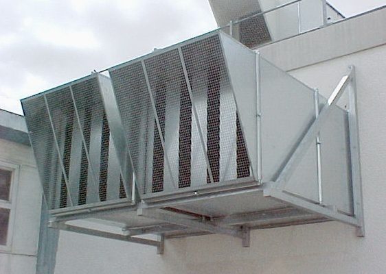
The acoustic grilles and panels designed by the Groupe Boët apply the same multi-criteria optimization principles to air-handling equipment installed on building facades or roofs. All of these industrial acoustic solutions are manufactured in accordance with ISO 9001 and ISO 19443 certifications, and comply with the EN 15085, ASME, RCC-M, CODAP, and CODETI standards.
For any acoustic treatment project involving a ventilation system—whether to reduce noise in the intake, discharge, or ductwork—the Groupe Boët offers a preliminary industrial acoustic study to determine the appropriate solution, supported by calculations and sized for the actual system. Contact the Groupe Boët teams at www.groupe-boet.com.